Picswr has separate forward and reflected calibration windows / processes.
These are accessed via
Menu | Calibration | Reflected Calibration
The forward calibration screen is used below to illustrate the software.
(The reflected screen differs only in having a 'Mismatch watts' setting).
If you are looking at this software for the first time, it would be useful to view and/or print the G3VPX default calibration information.
To view and print the current calibration summary, click Menu | Calibration | Calibration summary
To move to the help screen on this, click Calibration summary
You may wish to first look at the help screen Calswr - Load a calibration which explains the data.

This is the display on entering the forward calibration screen.
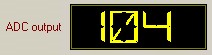
On switching to transmit, the LED-style ADC output indicator comes to life.
To perform forward calibration you can use a dummy load.
To perform reflected calibration you need a 'good mismatch' !!
Your calibration is totally dependant on the accuracy of your wattmeter !!
I used the rather fine cross needle meter on a Daiwa automatic tuner.
(For the higher reflected powers, I reversed the antenna and Tx connections and read the forward scale)
The calibration point (Id=1) remains at ADC = 0, watts = 0.
For your first entered point (ie: Id = 2), use DDS 8.1 to increase PicAStar's output to a readable low level on the wattmeter. (My first point was 0.34w)
The ADC level will display in the LED-style display
Now double click the ADC column Id=2 cell. The ADC value is entered automatically.
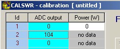
Now enter the wattmeter reading into Power column Id=2 cell

Now increase the PicAStar output in 1dB steps up to your maximum power level.
At each increment, repeat the ADC column double-click recording and the corresponding wattmeter reading data entry.
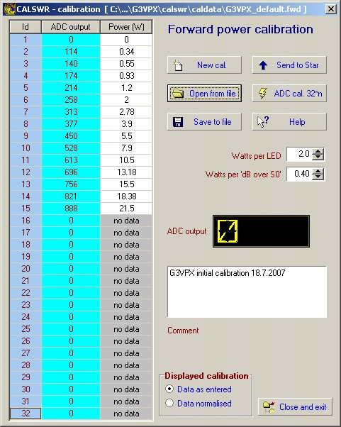
You should have well under 32 points. My initial calibration show above has only 15 points as above.
Normalising the calibration
Now click  or check 'Data normalised' in
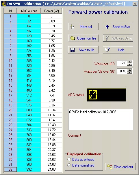
Calswr has effectively 'drawn a graph' using the initial points and then produced calibration points at thirty two ADC steps of 32 units.
(32*32 - 1 = 1023 - max ADC output for a 10 bit ADC)
The normalisation process uses linear interpolation between the entered calibration points.
These 32 power levels are stored in the Picswr PIC16F876 EPROM. They appear in the rightmost columns of the ADC calibration printout.
On transmit, Picswr divides the current ADC output by 32 and uses the resulting number ( n = 0 to 31) to look up the power level. It actually also looks up the next adjacent power level (n+1) and uses simple linear interpolation between levels n and n+1 for improved accuracy.
Calswr's main screen LED power displays use exactly the same process with same 32 calibration points.
Saving your calibration to disc
Click ![]() which opens a Save dialog window:
which opens a Save dialog window:
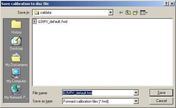
The filename box shows the existing default calibration filename. You need to change this to a new filename for your calibration and then click then Save button. You have no control over the file suffix:
Forward calibration files are all .fwd and reflected calibration files are all .ref.
When you save the calibration to disc, it becomes the default calibration (forward or reflected) whose filename is stored in the registry. Thereafter, on return to the main window or whenever you restart Calswr, it will be loaded as the calibration of the main window display.
You need to send this new calibration to Picswr in PicAStar.