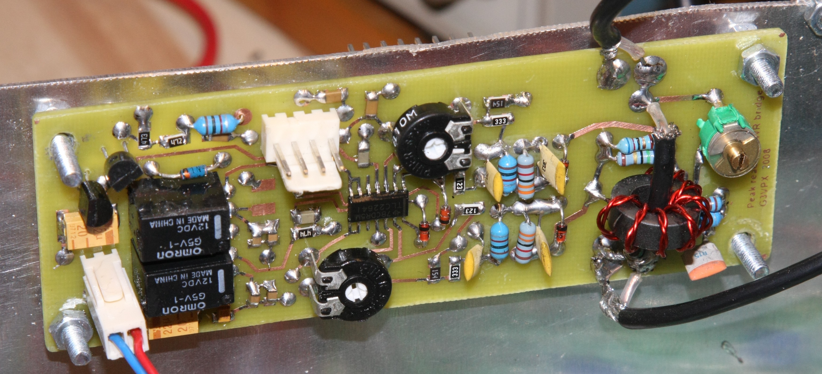
A peak reading SWR bridge
It was promised over a year ago for my PICSWR project.
It is working in the prototype breadboard constructed TxrAVR controlled Picastar
- see www.homebrew-radios.net
It has not yet been operated with PICSWR ... but PICSWR's calibration software is intended to work with any SWR bridge.
Schematics and layouts:
- peakswr_schematic.pdf
- peakswr_layout.pdf
- peakswr_top_copper.pdf (this image is mirrored)
- peakswr_bottom_copper.pdf
Original Pad2Pad files:
PeakSWR Images
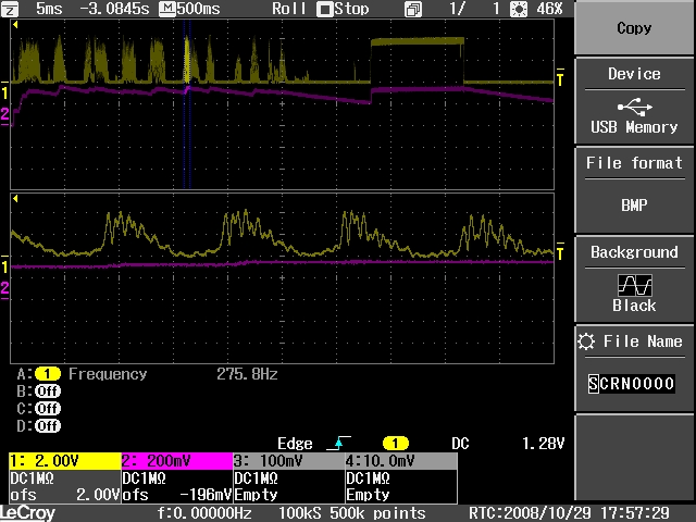
- PeakSwr waveforms with 100w PEP Picastar SSB (7dB of compression .. and my low pitched voice!)
- Left side of trace is SSB - right is 1 second of steady carrier (with CW decrement = 1dB)
- Top trace (ch1
yellow) is the forward SWR bridge output (RFC3/C18) - time constant here approx
300uS
- Second trace (ch2 purple) is PeakSwr output on IC1 pin8 ( with long 2sec decay
time constant .. ie relays energised)
(NB: both channels are 2v/div - the difference in labelling is because ch2 hasn't been programmed for a 10x probe) - Lower traces are upper two traces expanded 100:1 (5ms/div instead of 500mS/div)
ie: my voice at apparently 275Hz + harmonics forming the modulation envelope)
Development
29th October 2008
Further observations:
Examining these traces after publishing them gives rise to possible improvement:
The purple trace suggests an output rise time in the order of 15ms. This works ok simply because
most speech bursts are longer than 15mS ... but its not perhaps ideal.
The mathematics of this is as follows:<>
The capacitor is 4uF (C22+C8+C9). Consider a voltage rise of 4v:
The stated op-amp output current is +/-10mA. (corrected)
Thus the maximum charging current is 10mA.
If this current were constantly applied:
Q = It = CV, therefore t = CV/I =
4*10-6 * 4 / 10*10-3 = approx 1.5mS charging
time /4 volts - 0.375mS/v
BUT .. as can be seen from the expanded waveform on the scope tracing, the input to the op-amp is not a constant level. It is in fact varying with the speech waveform. I am not sure what the average is but is probably 10% or less and explains the observed longer rise time.
So, if improvement is needed consider the following:
The 'hold' circuit is 470k and 4uF ie: R12*(C22+C8+C9). (now changed)
Changing this to 2M2 and 1uF would maintain the 2 second decay but the smaller
capacitor would reduce the output rise time by 4x.
This is probably the best course of action. (I tend to avoid high impedances
.... but with 1uF damping, this shouldn't cause a problem. The op-amp has
high Z FET input)
The time constant between bridge and amplifer is 300uS. Making this longer would help a bit.
However, the 300uS design was based on maximum modulation frequency of 3kHz.
A significant increase in this time constant would ? impair peak response.
The source of charging current is the RF bridge circuit and I dont know how
to calculate this.
The capacitor choice (C3+C18 and C2+C17) was influenced by the need for RF
filtering. At 2MHz, the total of 5nF has an impedance of 18R ... which is
not particularly impressive RF decoupling .... hence the use of a series 1mH
RFC (12k at 2MHz) with the 5uF shunt capacitance split 3n3 and 2n2 before
and after the RFC to make a low pass filter.
Note that there is a 100nF output decoupling capacitor (and another 100nF on the input to the AVR processor). Even if the (C22+C9+C8) is reduced to 1uF, the charging of this capacitance (0.2uF) is five times faster than the 1uF and so should not limit the achieve rise time.
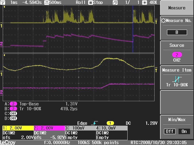
30th October 2008
Lower traces expanded 500x to observe output rise time
Hold circuit modified - C8 = 1uF, R12 = 2M2
- same time constant but theoretically 4x faster charging
From scope:
slew rate = 419.2 * 1.25 / 1.31
= 0.4mS/V ,or 1.6mS to rise to
the maximum of 4v
The speech bursts are much longer than 1.6mS and so a close approximation to
PEP should be obtained.
Output observed on a 1mA meter - looks good!