PicSwr
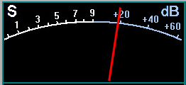
Provides forward and reflected power and SWR metering using the 12-LED display and the analogue S-meter (if fitted)
The hardware installation is an SWR bridge and a small board containing a PIC16F876 processor and an ST232N RS232 interface chip.
Calswr
is a PC-based calibration program for Picswr.
calswrsetup.exe installs Calswr on your PC together with all the necessary documentation and PIC software for Picswr.
PicSwr Layouts and Schematics
were produced using the Pad2Pad PCB layout program.
The .pcb files can be edited if you download a free copy of Pad2Pad.
The .pdf files were generated by printing from Pad2Pad to Adobe Distiller.
Known bugs/issues
Please let me know if you find anything!
Downloads
Download calswrsetup.exe
This is the easiest way to download and install calswrsetup.exe.
This installs the Calswr programme structure, help screens, documentation and the Picswr pic code.
All the files are then to be found in C:\Program files\G3VPX\Calswr\hardware
The individual files may also be downloaded from here:
- swrbridge_schematic.pcb
- swrbridge_schematic.pdf
- swrbridge_layout.pcb
- swrbridge_layout.pdf
- swrbridge_copper.pdf
Picswr_Help
Help files, software installation and updating, operating manual, and system calibration.PICSWR version information
Note that Calswr version numbering will change even if the upate does not affect Calswr.
- August 2007 - Version 1010
- - initial release version
- 20.11.2007 - version 1040
- -PIC 16F876-20 hex code modified to run with PicAStar DSP code version 2a02.XJP. The changes resulted from a change to the byte sequence of data sent from DSP to the Status board PIC. No change to CALSWR.
- 22.11.2007 - version 1050
- - PIC 16F876-20 hex code modified again to run with PicAStar DSP code versions onwards from 2a03.XJP. The changes resulted from a further change to the byte sequence of data sent from DSP to the Status board PIC. No change to CALSWR.
- 1.6.2008 - version 1060
- -Bug fixed whereby eeprom storage of data downloaded from PC to Picswr had interchanged
analogue S-meter fwd and refl W/db.
- Correction to Picswr schematic. Pin 8 of IC1 (Vss) to 0v. (was labelled +5v - but layout was correct connecting to 0v) - 24.11.2008 - version 1100
- - Hex code had switch set to XT (needs HS for 20Mhz Xtal) - I had switched this prior to programming in my MElabs programmer. I hadn't realised that the 'save' option modified the hex file. This problem was brought to light by someone with a programming device with no means to change to HS. The hex code is now set to automatically default to HS mode.
- 15.02.2009 - version 1110
- - Hex code fix of 1100 applied to a slightly earlier version - fixed.
