
(double click for high-res. versions)
Front view - push button and tri-colour
LED to right of mic socket are for SWR indicator system
which uses the 12-LED S-meter and is under development.
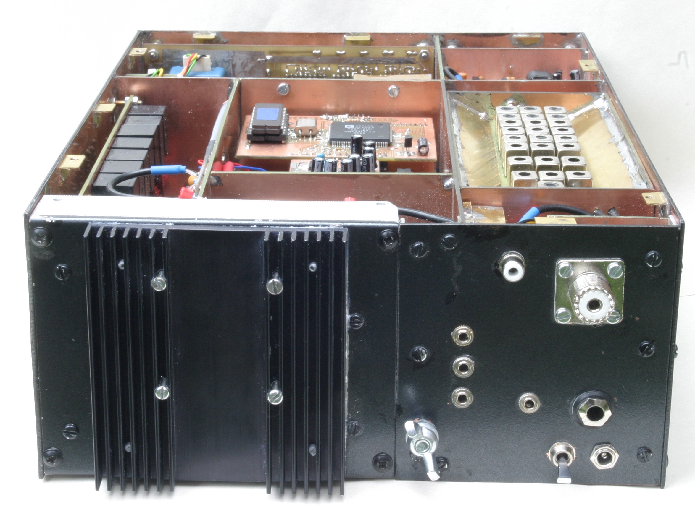
Rear view - phono for linear switching,
small jack sockets for PC link an audio out, CW key,
power, on/off switch, earthing terminal.
Note there are three PC link sockets - an extra one is to link the SWR PIC to
the PC calibration software.
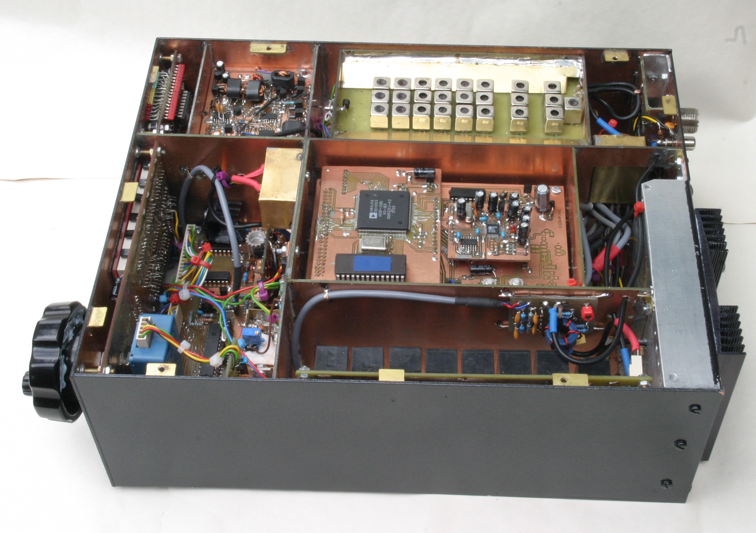
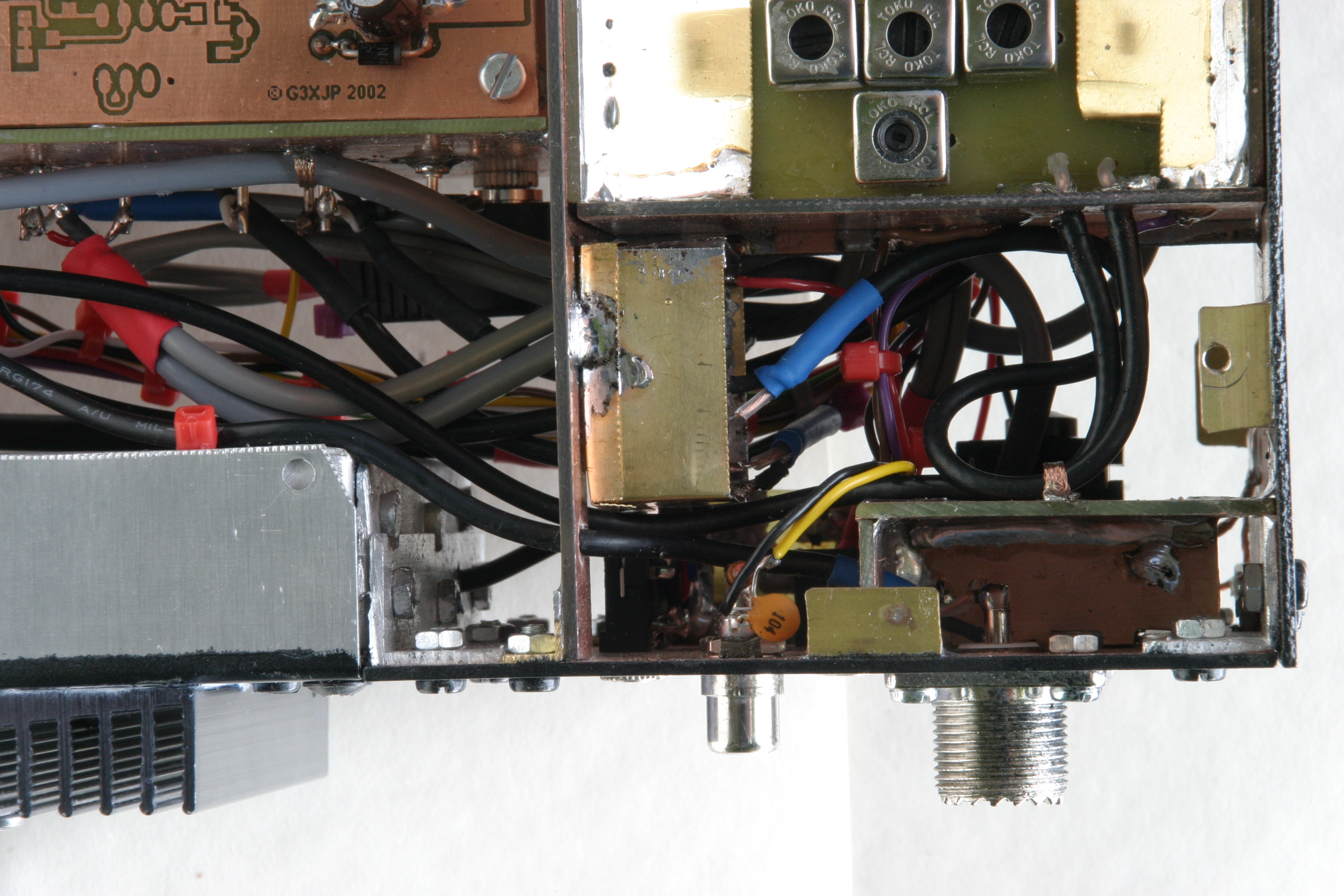
Side view - supports for top and bottom
are soldered pieces of brass angle.
SWR bridge unit now added botton right.
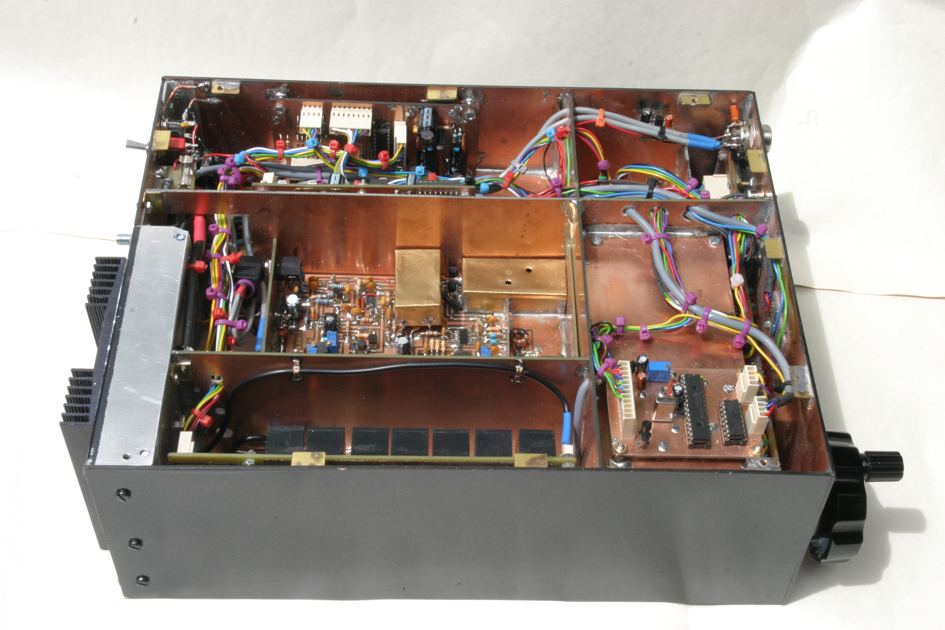
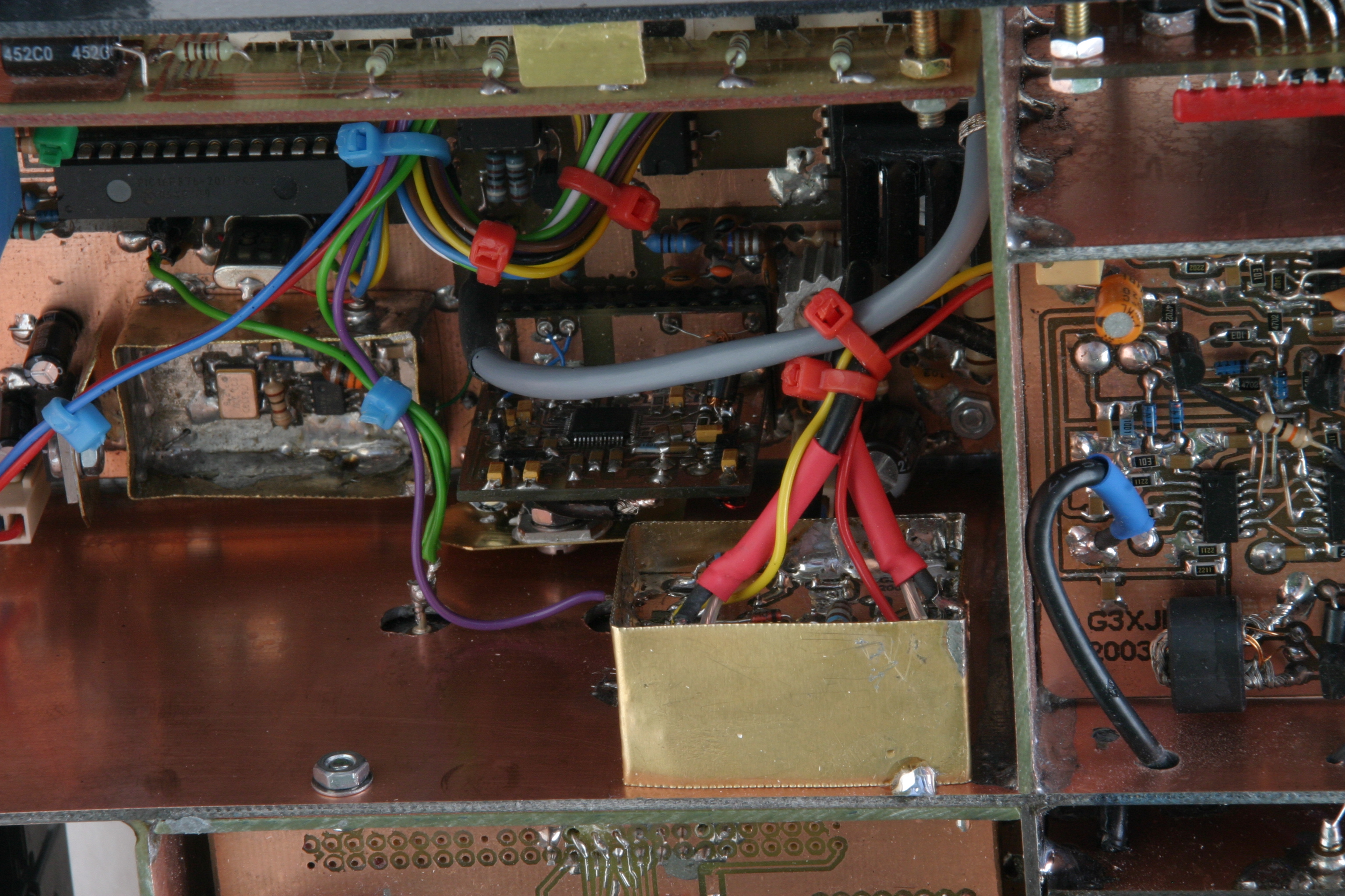
Side view - note the G6ALU logic and timer
boards mounted vertically beneath the BPF unit.
SWR PIC board added bottom right.
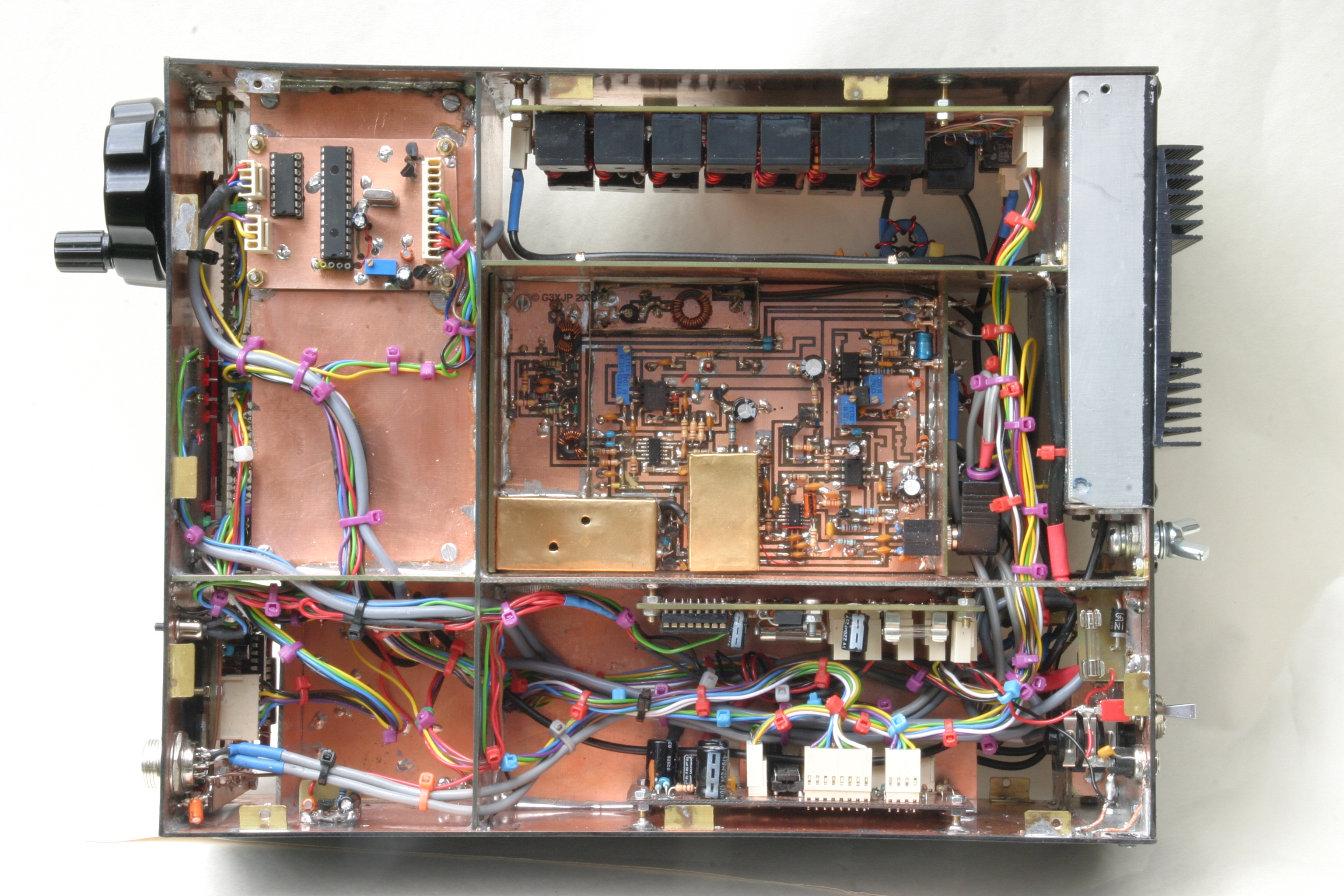
Underside view - fuse and reverse protection
diode for PA bottom right.
Screened power lead from fuse to PA is 5A mains core replacing central core
in a piece of RG58.
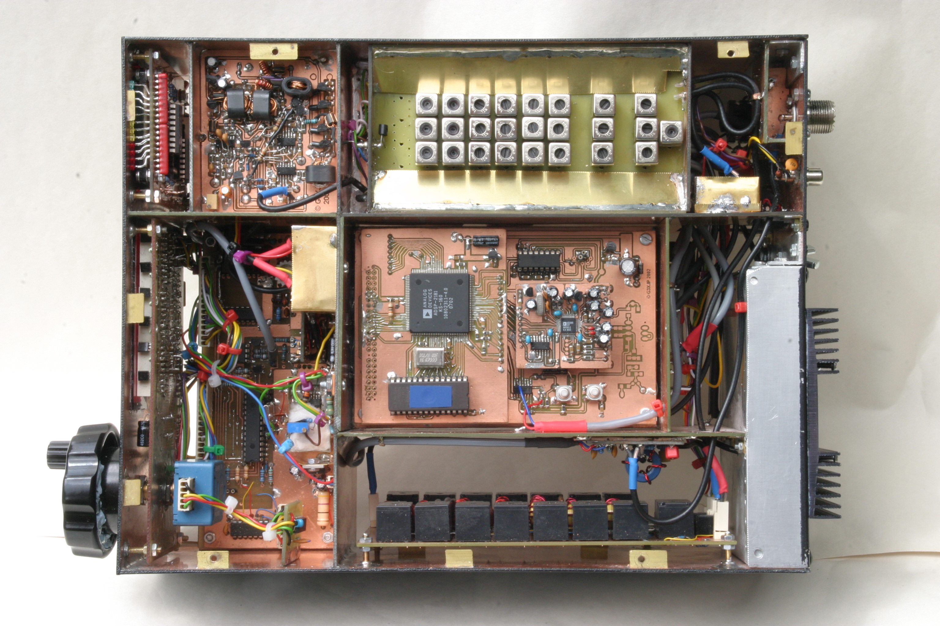
Top view - 7 LPFs - separate for 7 and 10Mhz.
Detail of PA compartment mounting, driver amp in brass box and screened compartment for antenna soclet.
DDS filter in brass box
Pletronics 200MHz osc unit middle left - before addtion of Harry (G3HNR) heater.

Harry (G3HNR) heater / temp control unit added to crystal oscillator. 8v regulator for this at top.
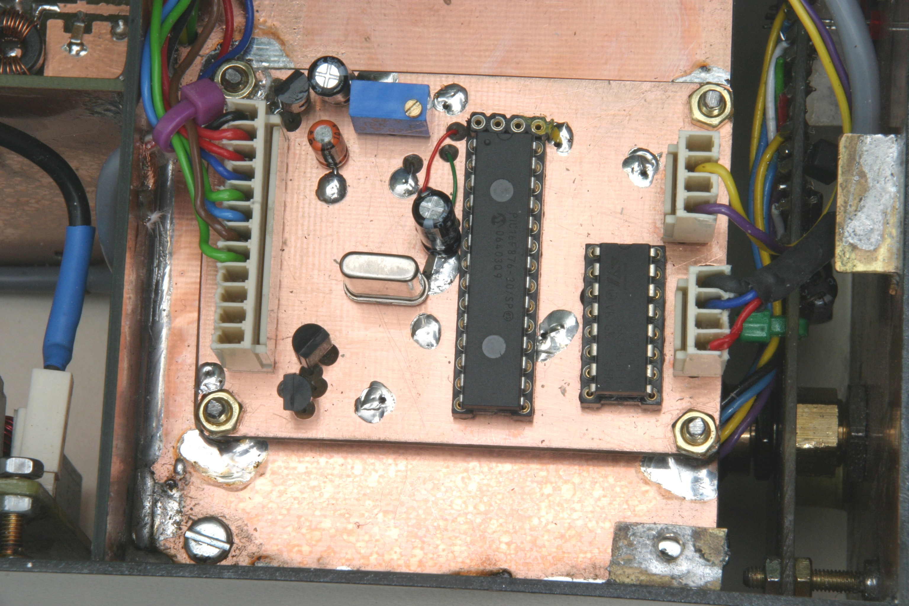
PICSWR board. Working but much work to
do on calibration software.
Use PIC16F876 + 20Mhz Xtal. Other chip is ST232 for RS232 communication with
calibration software on PC.
Forward and reflected voltage from SWR bridge are fed to two ADC inputs of the
PIC.
On transmit, the PIC sends serial data to the status board 12-LED display for
forward or reflected display.
A small push button and a triclor LED on the front panel allow stepping through
Tx options:fwd -refl.- low power
refl - ?swr -Star default.
On receive the PIC passes serial S-Meter telemetry from the DSP unit straight
through to the 12-LED display.

SWR bridge installed in LPF enclosure

SWR bridge close up.