
The Specs
- This amplifier uses G6ALU's excellent board design (- see his website)
- The amplifier uses a pair of SD1487 transisitors (obsolete now I think)
(I am building another for my G3VPX transceiver using a pair of Toshiba 2SC2879 transistors) - The amplifier plus a low pass filter board is housed in a case constructed from double sided PCB.
- The heat sink is RS Components
part number 271-864 (1.0degC/W,100x120x37mm)
- this does not not need a fan for 100w SSB operation even with speech processing on. - The LPF unit has seven filters
(160m, 80m, 40m, 30m, 20m, 17&15m, 12&10m)
The filters use T80-2 and T80-6 toroids and silver mica capacitors.
Mods & Comments
The design intended 12volts relays.
The relays can be obtained from RS Components.
Many months previously, I obtained 50 relays from China via eBay for a very
low cost.
I installed them in the LPF unit and noted the high current consuption and that
they were running very warm.
- I had forgotten that they were for 5v operation!!
- This explains the presence of a 6v regulator and heat sink on the board!!
- It is not catered for in the PCB layout on the basis that anyone else would
use 12v relays!!
The eight relay pairs (7 LPF and
the bypass relays) are controlled by a PIC 16F876-20 processor.
The PIC outputs drive 7 LEDs and a 7-Darlington chip to drive the relays.
A push button steps between the seven filters.
A serial 9600 baud link to Picastar
allows LPF selection to occur automatically when Picastar changes band.
Picastar's internal PIC to DSP telemetry includes band change codes.
These are fed to the PICs UART receive input.
(Please note that a PIC16F876 running at 4MHz does not support 9600 baud on
its UART ... hence a 20Mhz PIC)
So far I have published on this site photos of the unit and of spectrum analyser filter responses. I will publish a schematic, PIC code and LPF L and C values soon.
Photoalbum
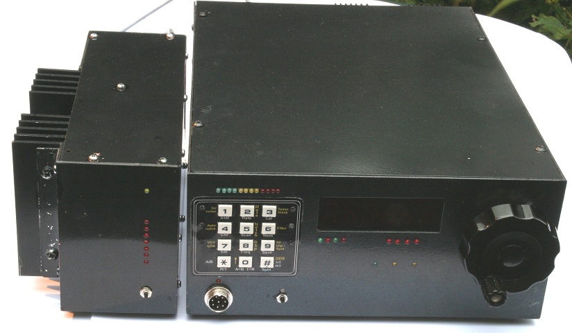 Photos - 100w PA
Board
 Board layout (pdf)
LPF Design
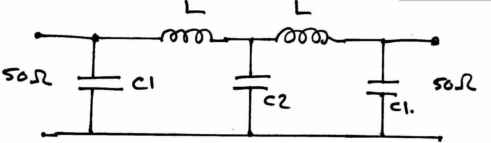
100w PA unit - Low pass filter details
Capacitors all silver mica
Inductors on T80-2 and T80-6 cortes from Amidon etc
| Band | C2 | C1 | L |
|---|---|---|---|
| 160 | 2200pF | 1500pF | 30 turns 22swg on T80-2 |
| 80 | 1500pF | 820pF | 21 turns 20swg on T80-2 |
| 40 | 820pF | 430pF (390+39) | 16 turns 20swg on T80-2 |
| 30 | 560pF | 330pF | 13 turns 20swg on T80-2 |
| 20 | 390pF | 220pF | 12 turns 20swg on T80-6 |
| 15/17 | 280pF (200+82) | 150pF | 9 turns 20swg on T80-6 |
| 10 | 180pF | 100pF | 8 turns 20swg on T80-6 |